Due to the smaller size of the Vertical Axis Wind Turbine, the Coefficient of Power (the ratio to convert wind power to electricity) is lower than Horizontal Axis Wind Turbine. Therefore, as every researcher in the world, we aim to improve the Coefficient of Power of the Vertical Axis Wind Turbine.
Basically, there are two types of approaches to improve the Coefficient of Power: Active Flow Control and Passive Flow Control. Active Flow Control refers to some sort of energy input that is necessary for active flow control to manipulate the flow, while passive flow control methods manipulate the flow by not requiring any exterior energy resources.
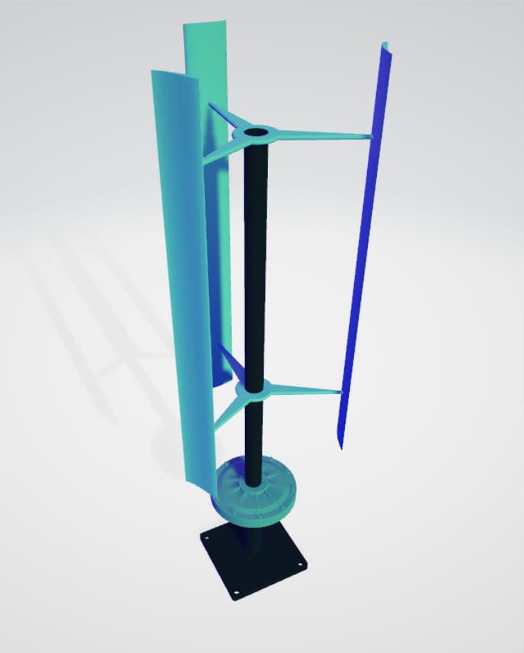
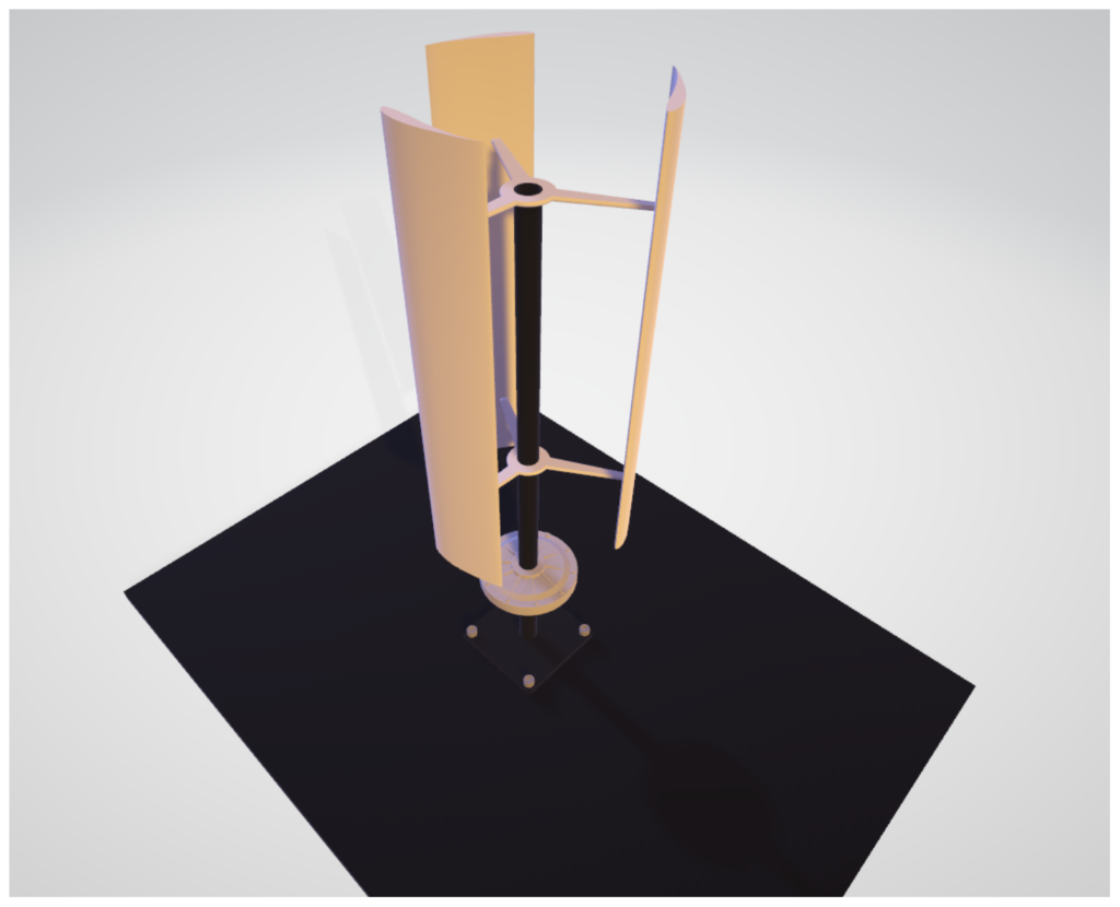
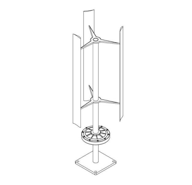
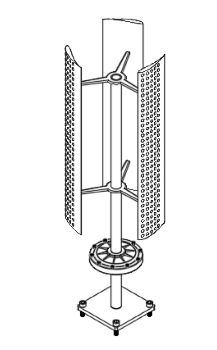
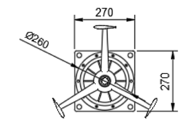
Basic Version Design Characteristics
Design features:
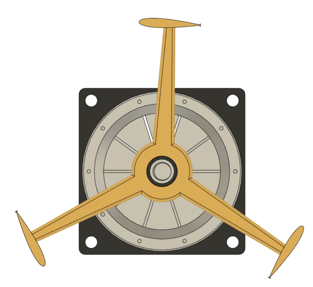
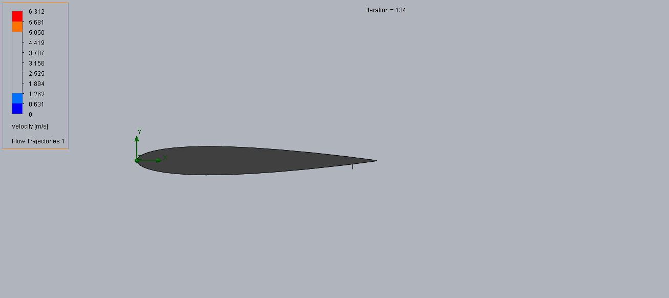
-Self Starting: This turbine version has a high lift low Reynolds number airfoil to allow starting at low wind speed. Selig 1210 Airfoil.
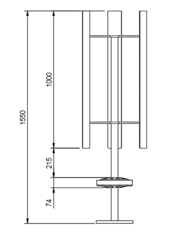
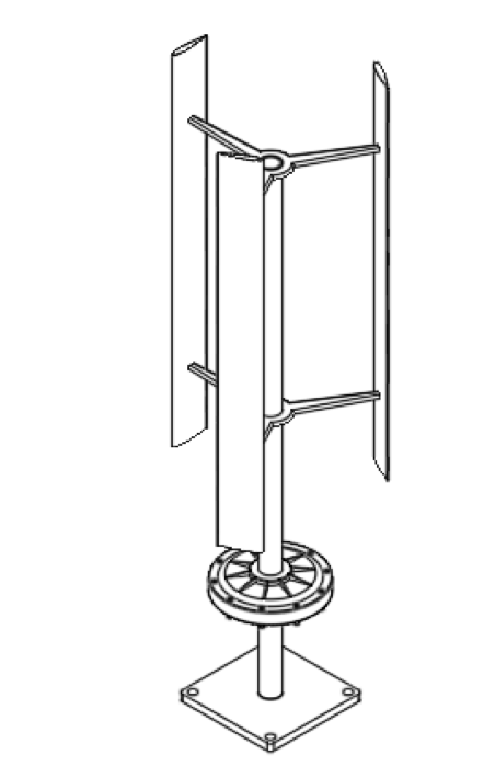
-Compact Size: Rotor Diameter 0.5 m, Rotor Height 1.0 m
-Low Weight: The turbine blades will be made out of extruded Aluminum has a low weight.
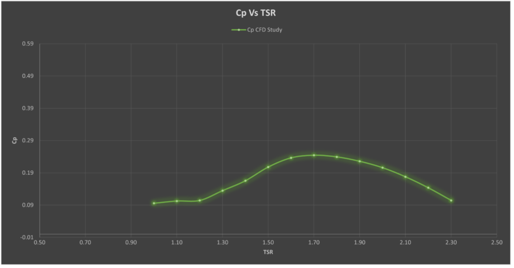
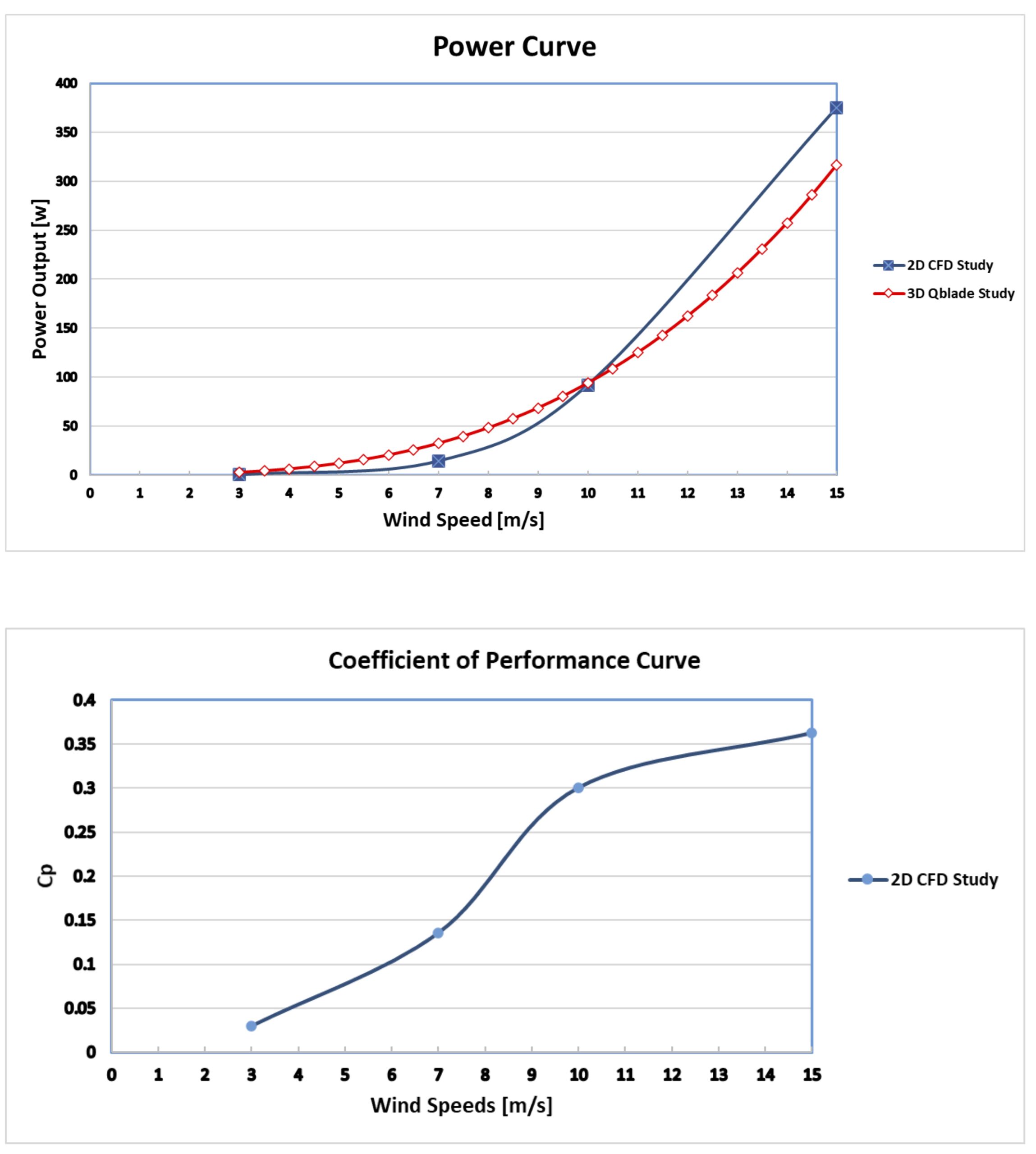
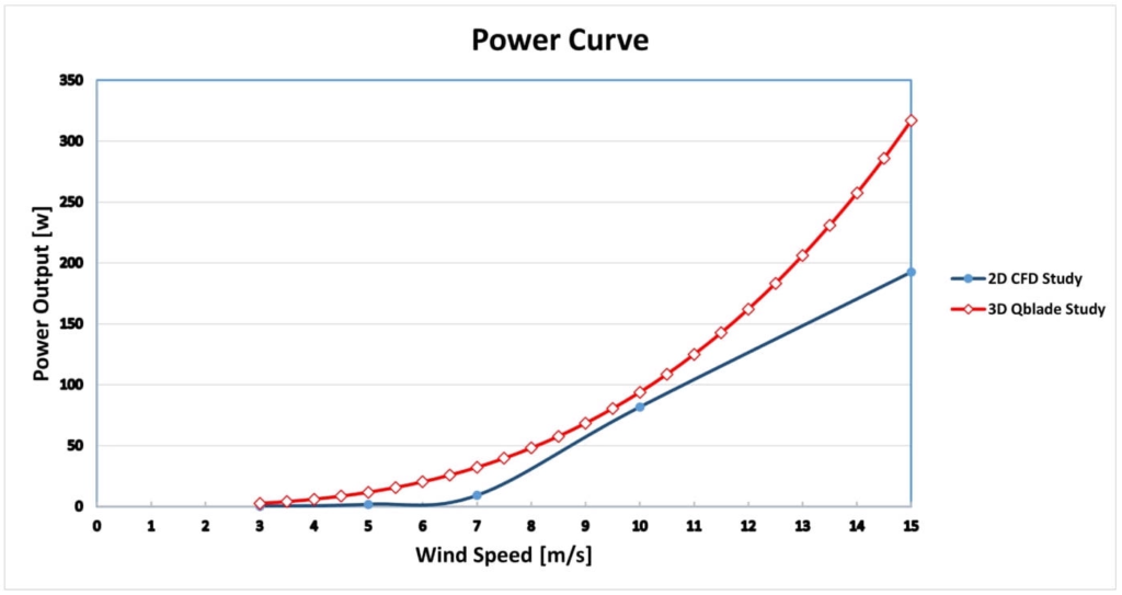
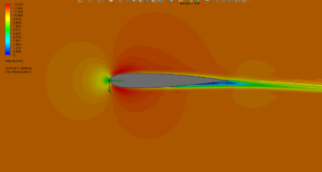
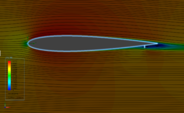
The Coefficient of performance Cp curve at a range of tip speed ratios is plotted from the CFD study as follows:
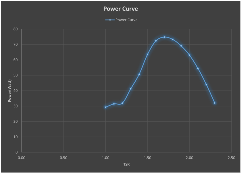
Power Curve at different TSR
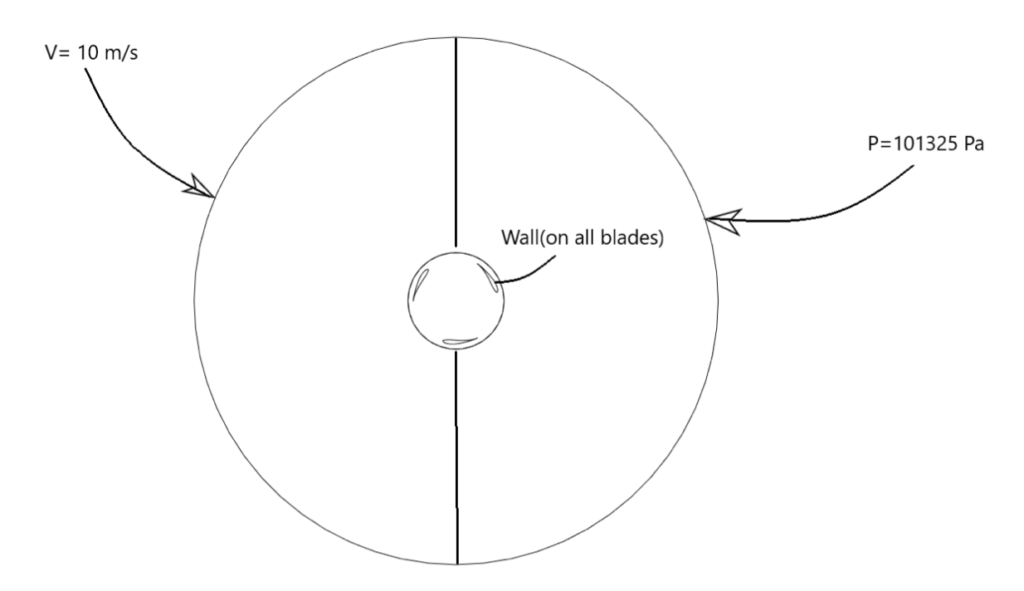
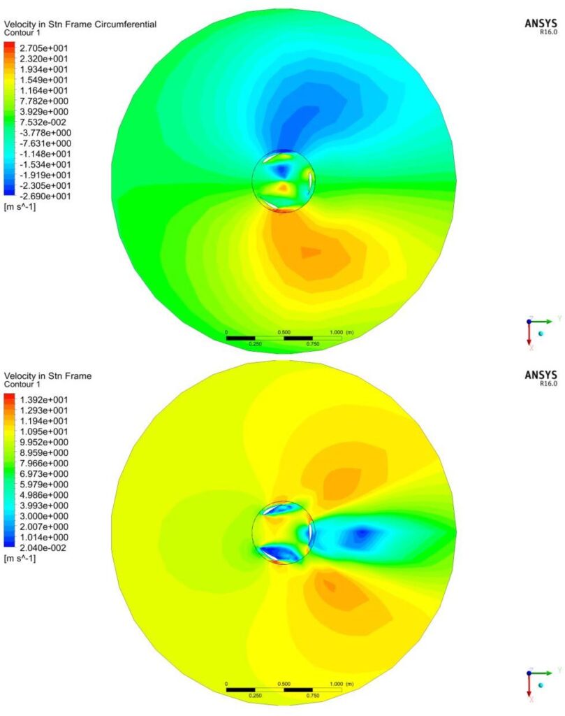
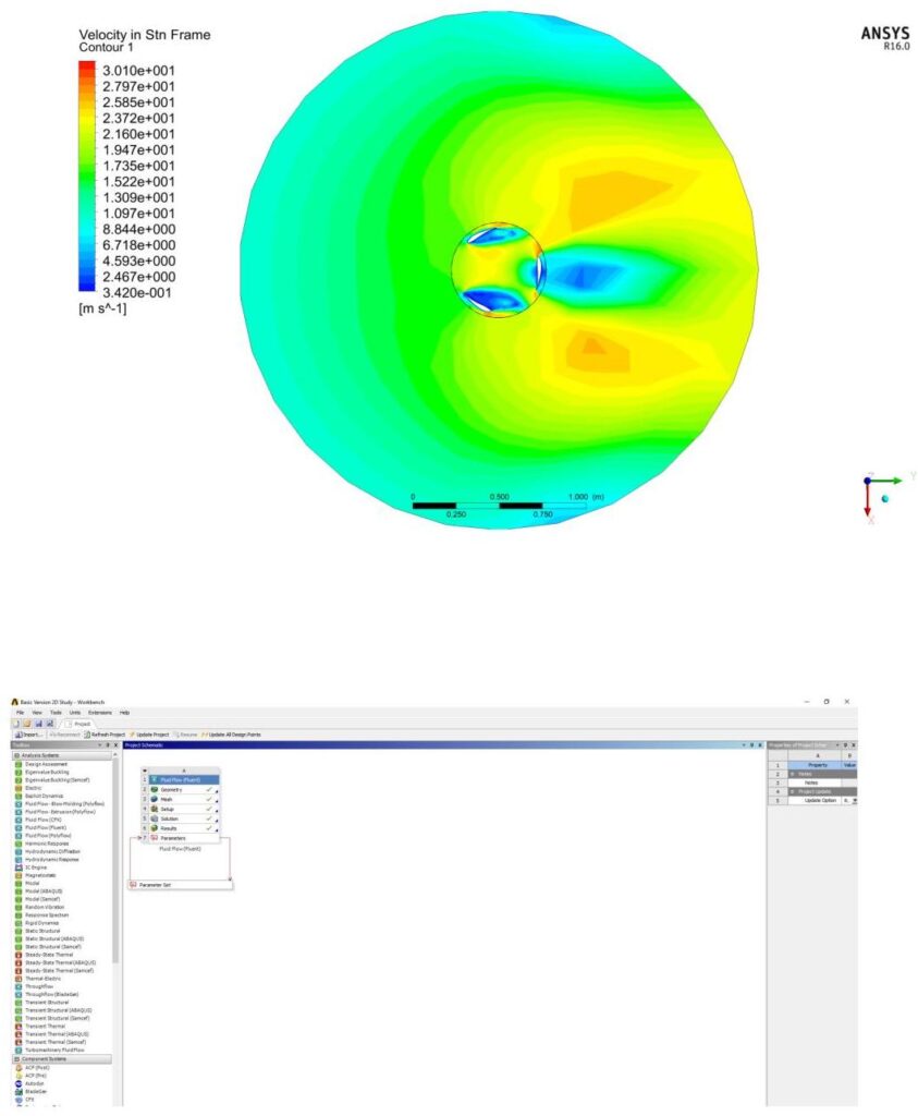
CFD Process Steps:
The Turbine design is analyzed by CFD study in Ansys workbench to calculate the performance curve of the turbine:
To accomplish this goal we follow these steps:
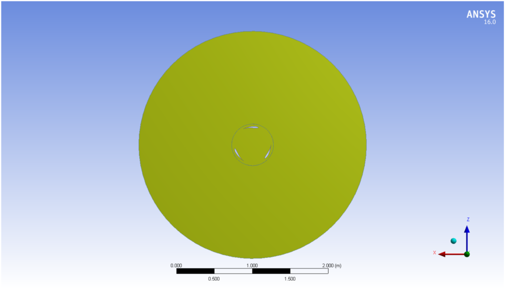
1. A simplified geometry was created to reduce the calculation time of the CFD solver. Geometry was created in Autodesk Fusion 360 and then exported to IGES format.
2. Start an Ansys workbench project and select the fluid flow module of Fluent.
3. Open the Design modeler by double-clicking the geometry tab.
4. Import the 2D geometry that was created in IGES format earlier.
5. Do some minor editing of the geometry in the Ansys design modeler to simplify the geometry for the meshing process.
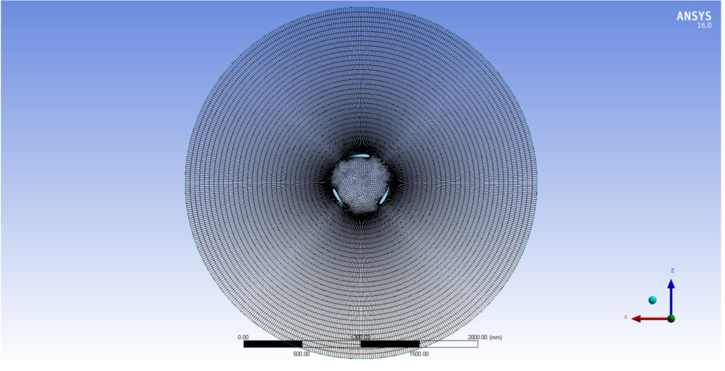
6. Open Ansys Meshing from the Mesh tab and start to apply meshing methods to the fluid domains with appropriate sizing.
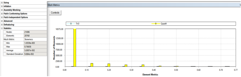
7. Check the generated mesh metrics like mesh quality, aspect ratio, and Skewness. To ensure the smooth running of Ansys fluent solver.
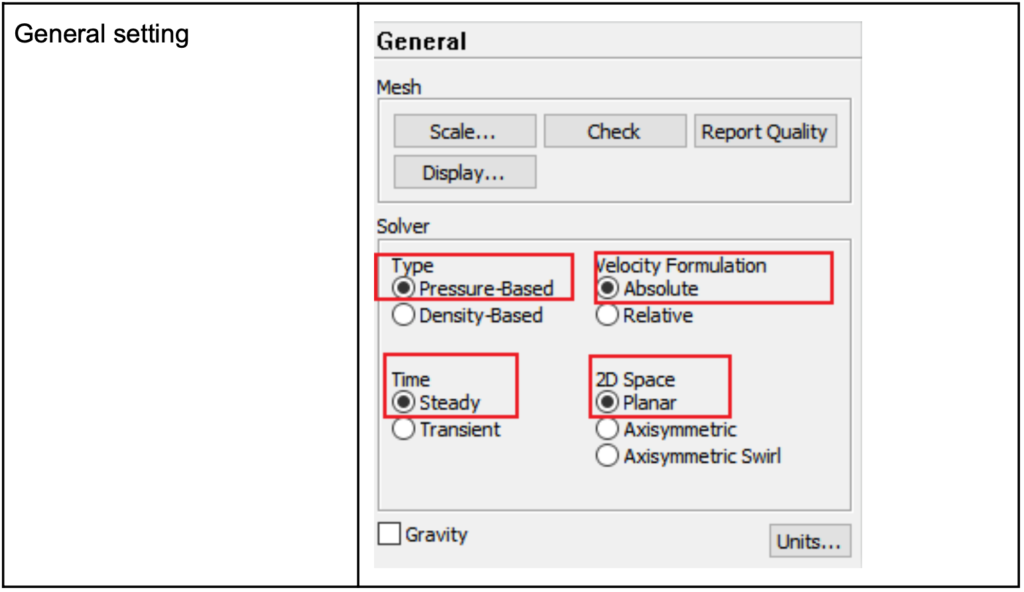
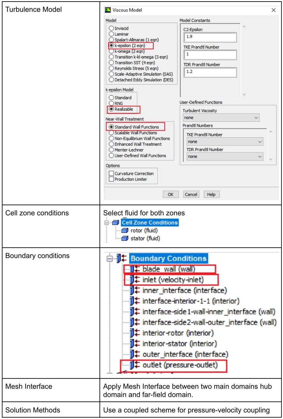
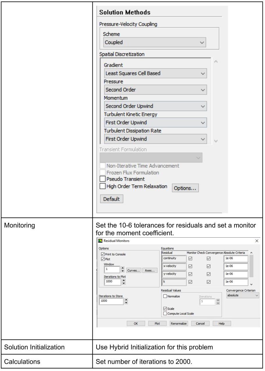
8. Open Fluent solver and apply the solver settings as follows:
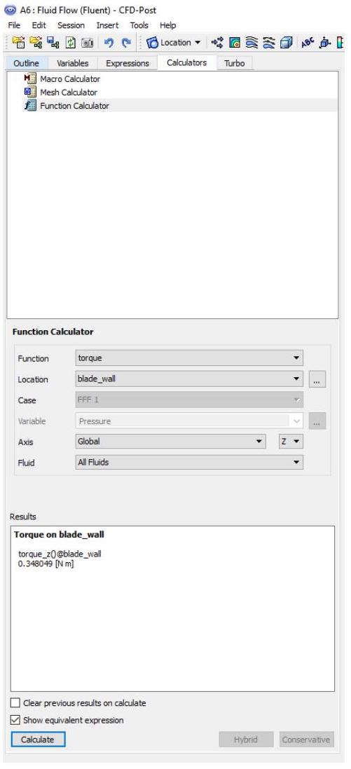
9. Open the CFD-post by double-clicking the results Tab, then start to present the results and calculate quantitative values such as torque values to calculate the power of the turbine.
Turbine predicted Performance
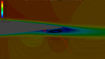
Dimpled Blade Design (Golf Balls Effect)_Passive Flow Control
At WindCycle we research and develop technologies to improve the design and efficiency of VAWT by using Passive Flow Control (PFC) techniques to increase the lift force and the corresponding torque of the turbines.
The goal is to enhance turbine efficiency by using passive techniques where no energy needed to control the flow separation like moving flaps, DBD…etc.
Design features:
This turbine version has a high lift low Reynolds number airfoil to allow starting at low wind speed.
The straight blade has a pattern of dimples on the suction side. The dimples built like the dimples on the golf ball. Several studies confirmed that dimples on golf ball increase the lift and reduce the drag due to the delayed boundary layer separation unlike smooth undimpled surfaces.
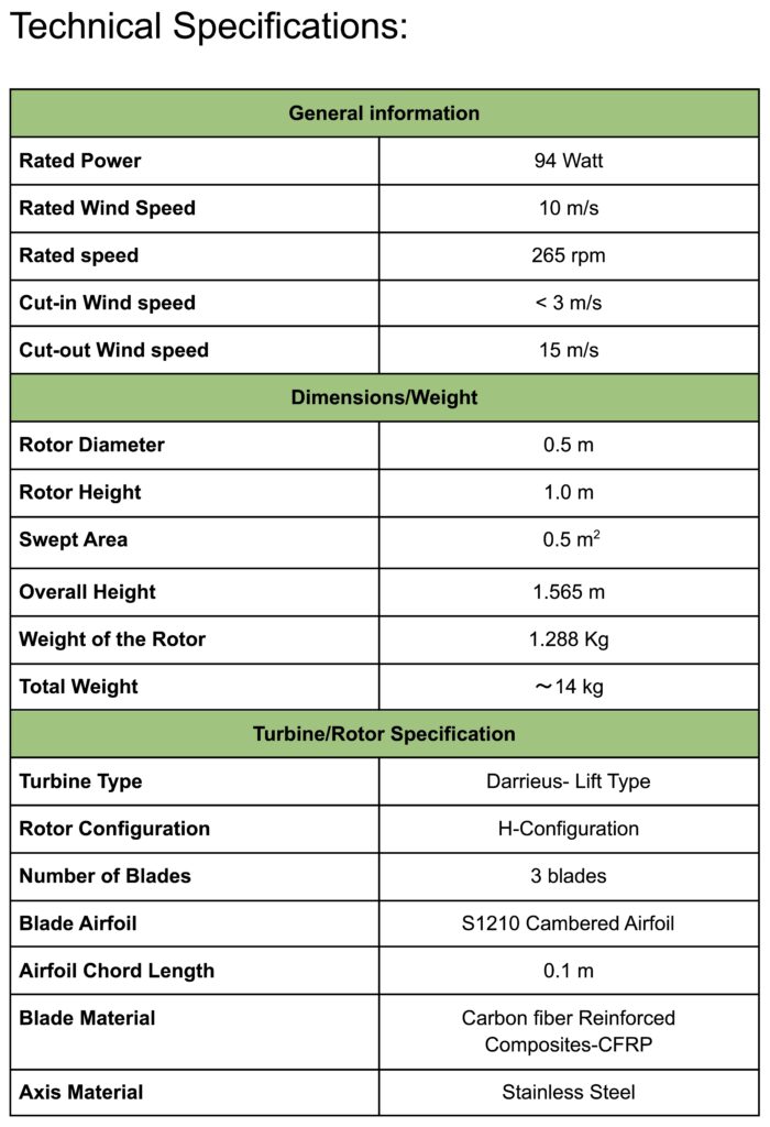
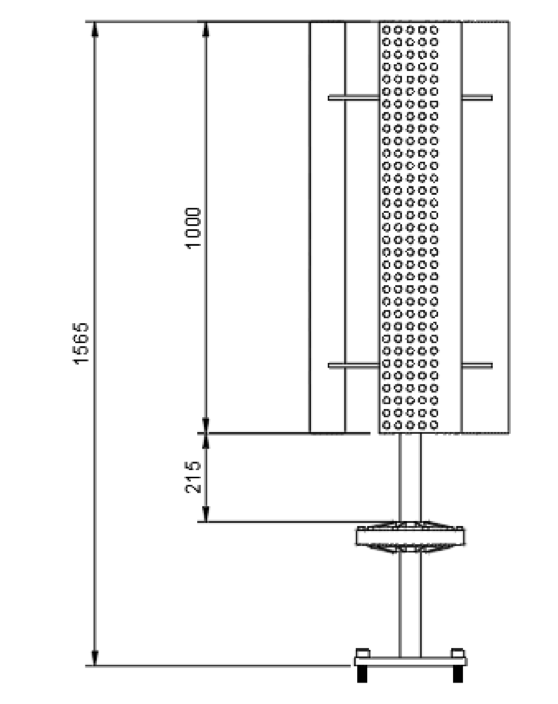
Dimensions:
Rotor Diameter(m)
0.5
Rotor Tall (m)
1.0
Swept Area (m2)
0.5
Overall Height
1.56
Expected Performance:
Increased performance by modifying airfoil surface topology using dimples has been proven by several studies. An experimental work conducted at Ohio university by Lake JP [1] postulated that using dimples in a vane of low-pressure turbine results in loss reduction ranging from 5.1% at 100K Reynolds number to 51.7% at 50K Reynolds number. Other CFD study conducted by Arun K.K et al. [2] presented that a performance increased by 14.7% in dimpled blade compared to plain blade.
References
Lake JP. Flow separation prevention on a turbine blade in cascade at low Reynolds number. PhD thesis. Ohio: Air Force Institute of Technology; 1999
Rajagopal, Ajay & Kumar, Sam. (2018). Analyzing the Effect of Dimples on Wind Turbine Efficiency Using CFD. International Journal of Applied Engineering Research.
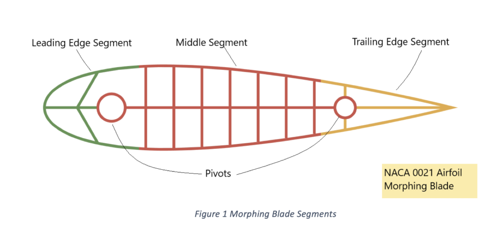
Morphing Blades Design_Active Flow Control
The study of morphing blades technology is a novel way of implementation in VAWT to get high aerodynamic performance.
Due to the angle of attack of blade continuously changing by the rotation of the turbine, morphing wing technology helps to increase the energy harvesting capability of the turbine and decrease the Aerodynamic loss.
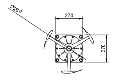
In this design the first and third segment of the blade are pivoted to the middle segment in specified locations as depicted in Figure 1.
These two segments will be actuated by a novel designed complaint structure mechanism.
The actuation mechanism is designed to minimize the applied effort by the actuator and maximize the stiffness with considering the external loading.
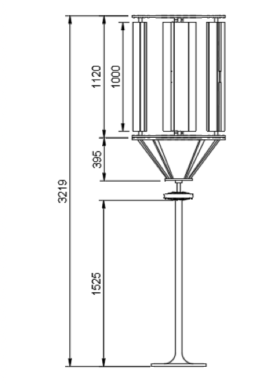
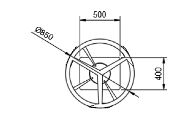
Dimensions:
Rotor Diameter(m)
0.85
Rotor Tall (m)
1.0
Swept Area (m2)
0.85
Overall Height
3.219
Expected Performance:
Currently, morphing wing technology receiving a significant interest from the wind turbine community. Many research projects delivered in the aerospace industry related to morphing wing as described in review paper [1]. The Authors in paper #1 mentioned that: “Wittmann et al. (2009) postulated that 74% increase in lift coefficient could be achieved by maximizing wing area and camber”. In the wind turbine area, many numerical and experimental studies demonstrated the benefits of blade morphing. Keeping in mind cost, simplicity and safety factors, the next phase in the development of large wind turbines is the integration of these compliant structures into the blade design, ensuring a better energy capture while increasing the turbine lift [2].
References
Barbarino S, Bilgen O, Ajaj RM, Friswell MI, Inman DJ. A Review of Morphing Aircraft. Journal of Intelligent Material Systems and Structures. 2011;22(9):823-877. doi:10.1177/1045389X11414084
Lachenal, Xavier & Daynes, Stephen & Weaver, Paul. (2013). Review of morphing concepts and materials for wind turbine blade applications. Wind Energy. 16. 283-307. 10.1002/we.531.
Gurney Flaps Design_Passive Flow Control
Gurney Flap Design:
VAWT aerodynamic performance is enhanced by redesigning the blades using a Gurney Flap (GF) as passive flow control technique
It enhance turbine efficiency by using a passive flow control technique where no energy needed to control the separation of the boundary layer.
Design features:
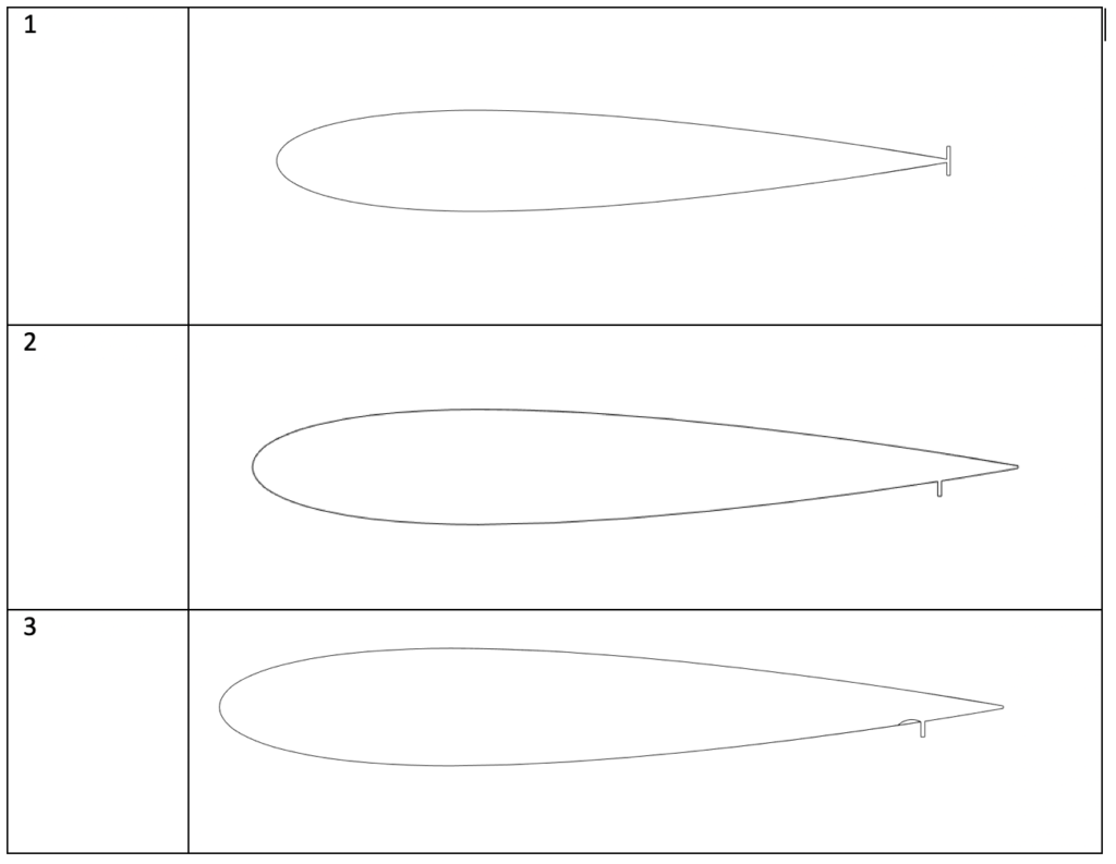
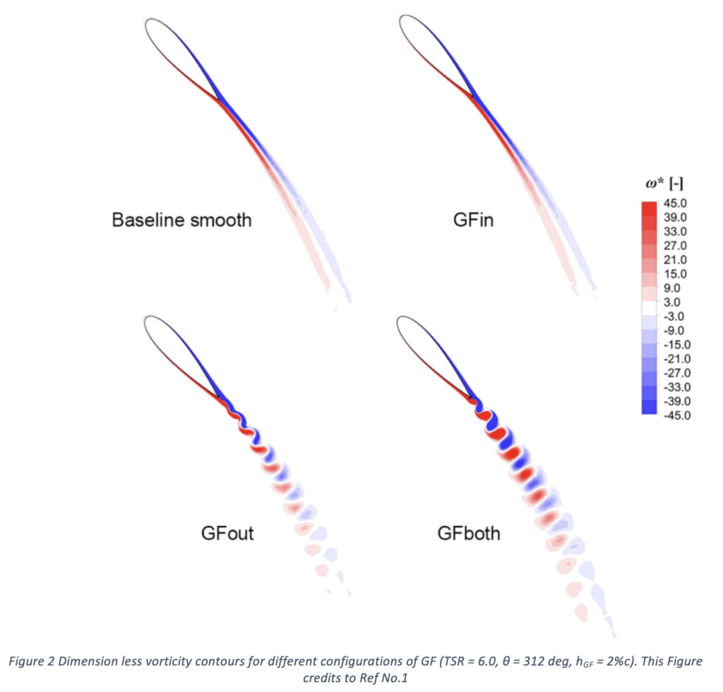
Symmetrical NACA 0015 airfoil selected to be as turbine blade and a gurney flap is added in three different configurations as following:
Symmetrical gurney flap at the blade trailing edge on both pressure and suction side.
Gurney flap on pressure side upstream the trailing edge.
Gurney flap as on configuration #2 with inward dimple.
In previous studies, these three configurations showed a better aerodynamic performance in terms of lift increase and delay of the onset stall.
Dimensions:
Rotor Diameter(m)
0.5
Rotor Tall (m)
1.0
Swept Area (m2)
0.5
Overall Height (m)
1.565
Expected Performance:
Bianchini et al [1] studied numerically three configurations of gurney flaps and they obtained power enhancements about 20% for some configurations. Other CFD study conducted by Shukla et al. [2] on different Airfoils presented that the configuration of using a combination of inward dimples and gurney flap achieved the best values of drag coefficient (CL) of 1.133 at angle of attack 12o. This was for NACA 0015 airfoil.
References
Bianchini, Alessandro & Balduzzi, Francesco & Di Rosa, Daniele & Ferrara, Giovanni. (2019). On the use of Gurney Flaps for the aerodynamic performance augmentation of Darrieus wind turbines. Energy Conversion and Management. 184. 402-415. 10.1016/j.enconman.2019.01.068.
Shukla V, Kaviti AK. Performance evaluation of profile modifications on straight-bladed vertical axis wind turbine by energy and Spalart Allmaras models. Energy 2017;126:766e95