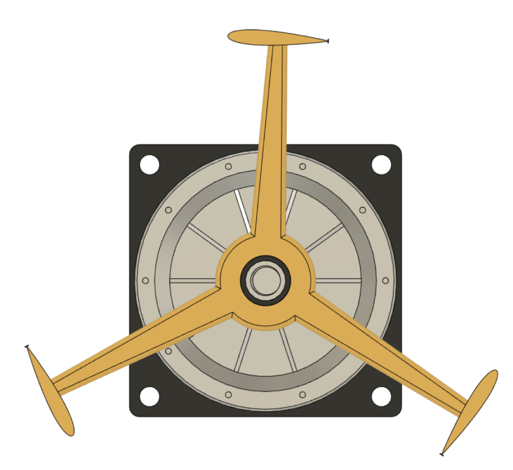
VAWT aerodynamic performance is enhanced by redesigning the blades using a Gurney Flap (GF) as passive flow control technique
It enhance turbine efficiency by using a passive flow control technique where no energy needed to control the separation of the boundary layer.
Design features:
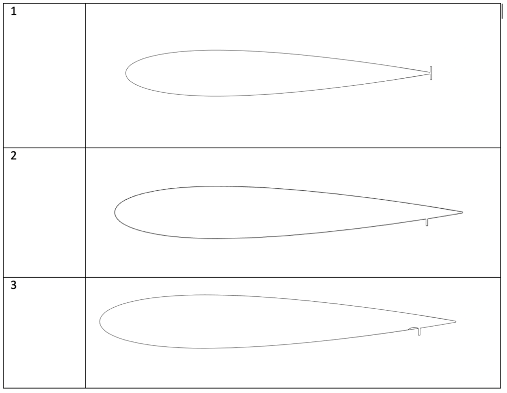
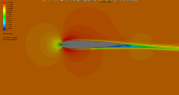
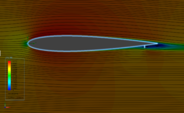
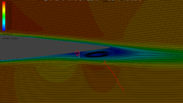
Symmetrical NACA 0015 airfoil selected to be as turbine blade and a gurney flap is added in three different configurations as following:
Symmetrical gurney flap at the blade trailing edge on both pressure and suction side.
Gurney flap on pressure side upstream the trailing edge.
Gurney flap as on configuration #2 with inward dimple.
In previous studies, these three configurations showed a better aerodynamic performance in terms of lift increase and delay of the onset stall.
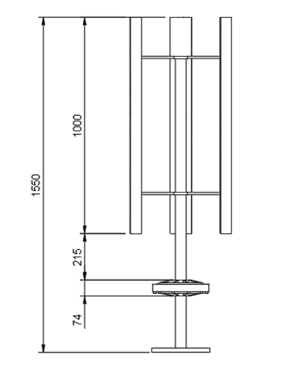
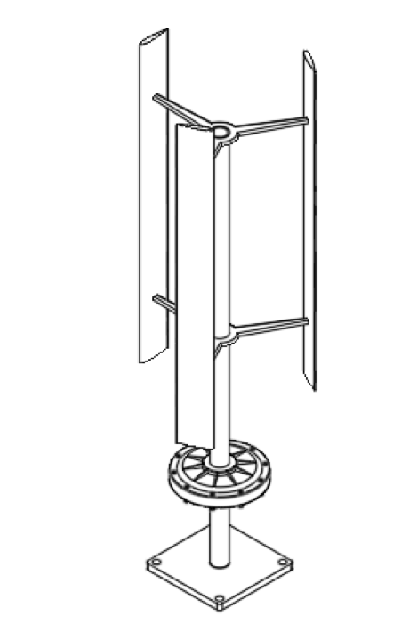
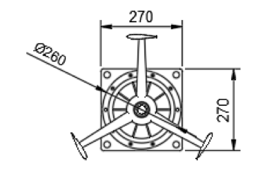
Dimensions:
Rotor Diameter(m)
0.5
Rotor Tall (m)
1.0
Swept Area (m2)
0.5
Overall Height (m)
1.565
Expected Performance:
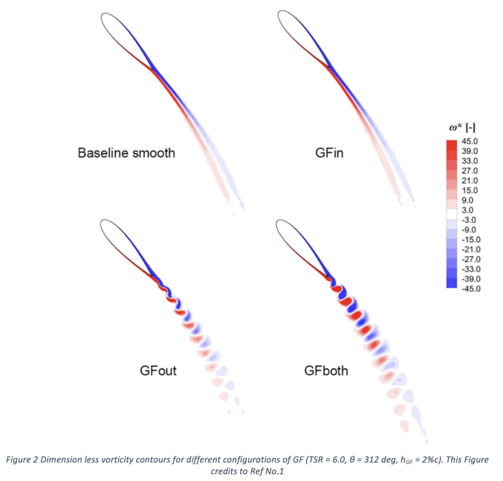
Bianchini et al [1] studied numerically three configurations of gurney flaps and they obtained power enhancements about 20% for some configurations. Other CFD study conducted by Shukla et al. [2] on different Airfoils presented that the configuration of using a combination of inward dimples and gurney flap achieved the best values of drag coefficient (CL) of 1.133 at angle of attack 12o. This was for NACA 0015 airfoil.
References:
Bianchini, Alessandro & Balduzzi, Francesco & Di Rosa, Daniele & Ferrara, Giovanni. (2019). On the use of Gurney Flaps for the aerodynamic performance augmentation of Darrieus wind turbines. Energy Conversion and Management. 184. 402-415. 10.1016/j.enconman.2019.01.068.
Shukla V, Kaviti AK. Performance evaluation of profile modifications on straight-bladed vertical axis wind turbine by energy and Spalart Allmaras models. Energy 2017;126:766e95